Views: 0 Author: Site Editor Publish Time: 2026-08-12 Origin: Site
Lifting capacity is functionally meaningless without a stable foundation. A Truck Mounted Crane is only as capable as its outrigger system allows. Gravity never takes a day off. Mounting a high-capacity lift mechanism onto a mobile chassis creates a volatile center of gravity. You must solve this core engineering challenge before every single job. Heavy payloads shift rapidly. They threaten to overturn the entire vehicle if left unsupported.
We introduce outriggers not just as a physical accessory, but as your primary load-bearing interface. You will learn how they alter fundamental physics. We will explore which hardware configurations perform best in specific environments. You will also understand how to master ground bearing pressure. Fleet managers must evaluate these structural systems closely. This strict diligence prevents catastrophic tipping. It guarantees job site safety. Proper setup protects your crew and your valuable equipment. Let us dive into the mechanics of ultimate stability.
Outriggers fundamentally alter the tipping axis, shifting the crane's fulcrum outward to counter heavy, dynamic loads.
Selecting between swing-out and retractable outriggers depends heavily on chassis constraints, deployment speed requirements, and lifting angles.
Ground bearing pressure (GBP) management is critical; an outrigger is only effective if the terrain beneath the pad can support the concentrated load.
Modern procurement requires evaluating automated safety features, such as Load Moment Indicators (LMI) and interlocking deployment sensors, to mitigate operator error (e.g., short-rigging).
You must view stability as a stringent risk management requirement. Asset protection relies entirely on a solid foundation. Unstable lifts warp the chassis permanently. They destroy expensive payloads in seconds. Furthermore, tipped equipment exposes your company to severe legal liability. Safety frameworks demand absolute precision. You cannot afford to guess when dealing with massive leverage forces.
Outriggers actively increase your operational footprint. They push the pivot point further away from the truck’s center of gravity. Engineers call this pivot point the tipping axis. By expanding this distance, outriggers increase the resisting moment. This mathematical force directly counters the load moment. It stops the load from pulling the vehicle downward. A wider stance mathematically guarantees a safer lift.
These stabilizers completely bypass the standard truck suspension system. Rubber tires cannot handle concentrated industrial weights. Outriggers isolate the crane's forces effectively.
The hydraulic cylinders push downward against the earth.
The system lifts the truck tires partially or fully off the ground.
The vehicle suspension unloads its stored energy.
The massive weight transfers directly through the steel legs.
The ground absorbs the entire operational force.
This process removes the bouncy, unstable nature of rubber tires. It creates a rigid connection between the lifting boom and the earth.
Supporting a stationary weight remains relatively simple. Absorbing kinetic energy presents an entirely different challenge. You must account for movement. A swinging load generates tremendous lateral momentum. Wind resistance adds unpredictable forces. When you rotate the boom quickly, you create centrifugal force. The outrigger system absorbs these dynamic shocks safely. They keep the chassis pinned firmly to the ground during violent energy shifts.
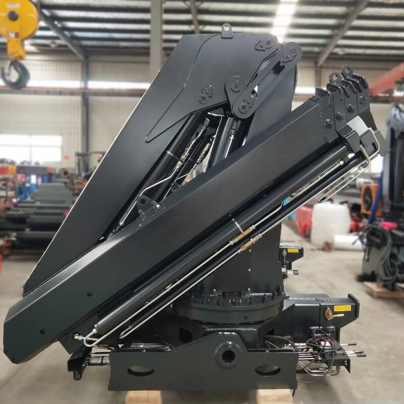
Hardware types vary widely based on operational realities. You must consider space constraints closely. Application requirements dictate your final choice. Complex setups need specific configurations. For example, a Knuckle Boom Crane demands highly adaptable stabilization. Its articulating nature creates unpredictable load paths. You must match the leg style to your specific daily obstacles.
Swing-out designs rotate outward from a fixed pivot point. They function like opening a heavy door.
Pros: They are often much lighter. The mechanical design remains simple and robust. They work highly effectively for tight installations located directly behind the cab. Maintenance crews love their accessible joints.
Cons: They require a completely clear swinging radius during deployment. You cannot open them if a wall blocks the path. Operators find them less ideal in heavily obstructed urban sites.
Retractable designs slide straight out from a hollow housing. They use internal hydraulic cylinders to extend horizontally before dropping vertically.
Pros: They deploy in a straight lateral line. You can position them much easier in narrow urban corridors. They often offer broader maximum spans. This extra reach increases your safe lifting capacity.
Cons: They consume more internal frame space. The sliding mechanisms require strict, regular maintenance. You must protect the internal tubes against grit, ice, and debris.
Match the hardware to your primary job site environment. Urban utility work demands straight-line deployment. Open construction sites accommodate wide-swinging legs easily. Review your typical staging areas. Assess the specific crane classification before purchasing. The right configuration saves hours of setup time weekly.
The maximum rated capacity means absolutely nothing if the soil yields. Ground failure causes many catastrophic crane accidents. You cannot ignore the surface beneath you. A strong hydraulic cylinder will easily punch through soft asphalt. It will sink deeply into wet mud. Emphasize ground evaluation on every single job.
Total operational weight concentrates into a tiny footprint. You must add several massive numbers together. Take the weight of the truck itself. Add the weight of the entire crane structure. Add the maximum payload weight. Finally, factor in the dynamic downward force. All this combined energy pushes through a very small metal shoe. Without intervention, the pressure easily exceeds soil limits.
Outrigger pads and crane mats distribute this extreme load. They spread downward forces over a significantly wider surface area. This distribution reduces the pounds per square inch (PSI) applied to the soil.
Material Types: UHMW plastic resists moisture, chemicals, and bending. Wood is much cheaper but degrades rapidly under stress.
Evaluation Criteria: You must calculate sizing ratios based on the maximum anticipated GBP. A heavier lift requires a mathematically larger pad surface.
Best Practices: Always center the metal shoe perfectly on the pad. Never use cracked or warped wood.
Soil bearing capacity fluctuates wildly. You must look for hidden dangers. Hidden underground voids destroy stability instantly. Recent excavations leave the earth dangerously soft. Heavy moisture turns solid ground into sliding mud. Always inspect the area thoroughly. Look for freshly patched asphalt, underground utility markers, and nearby retaining walls. Never set up blindly.
Buyers must scrutinize specific metrics during the decision stage. You cannot buy based on brand alone. You must map specific hardware features to your desired outcomes.
Hardware Feature | Primary Function | Operational Outcome |
|---|---|---|
Extended Span Width | Pushes the tipping axis further outward. | Increases load chart capacity at longer radiuses. |
Independent Controls | Allows unequal leg extension. | Enables perfect leveling on steep inclines. |
Pilot-Operated Valves | Locks hydraulic fluid inside the cylinder. | Prevents collapse during a sudden hose failure. |
Lightweight Alloys | Reduces overall assembly mass. | Preserves remaining legal highway payload capacity. |
You must match the outrigger span directly to the required load chart. A wider span equals higher capacity at a specific radius. It provides maximum leverage against heavy loads. However, massive spreads limit tight-site usability. You cannot deploy a twenty-foot spread in a narrow residential alley. Balance your maximum reach requirements against your typical physical workspaces.
You need the ability to lower each leg independently. This feature remains strictly non-negotiable. It allows precise leveling across wildly uneven terrain. If you operate on a hill, the downhill leg must extend further than the uphill leg. Paired controls force both legs down equally. They fail completely on slopes. Proportional valves give the operator smooth, millimeter-perfect adjustments.
Hydraulic hoses burst occasionally. You must prepare for this mechanical reality. Look for pilot-operated check valves. Manufacturers often call them holding valves. They integrate directly into the metal cylinder housing. They trap pressurized fluid securely. They prevent the leg from retracting if a hose explodes. This hidden feature saves lives during catastrophic pressure losses.
Heavy steel assemblies provide incredible rigidity. However, they reduce your legal payload capacity. Every pound of stabilizer equals one less pound of cargo. You must assess how the assembly's weight impacts the truck on the highway. High-tensile steel alloys offer a great compromise. They reduce physical weight while maintaining immense structural strength.
You must align operations with standard safety regulations. Organizations like OSHA and ASME dictate strict rules. They write these rules based on historical accidents. Compliance protects your crew from injury. It protects your equipment from destruction. Train your operators to view these standards as minimum requirements, not optional suggestions.
Space constraints tempt operators to deploy legs partially. The industry calls this dangerous practice short-rigging. It proves incredibly hazardous. It immediately invalidates all standard load charts. The crane loses its engineered leverage. It will tip over much sooner than expected. You must avoid short-rigging unless you possess specialized, dynamically adjusted load charts.
Modern equipment uses advanced sensors to stop human errors. You should demand these features on new purchases.
Position Sensors: These electronic systems detect leg extension. They confirm if an outrigger is fully extended. They verify the mechanical locks are engaged.
Interlocks with LMI: Advanced units feature intelligent Load Moment Indicators. They read the position sensors directly. They automatically derate the lifting capacity if they detect asymmetrical deployment. They simply will not let the operator lift an unsafe load.
Mandatory pre-lift visual inspections save lives. Crews must verify pad placement visually before touching the joysticks. They must check the cylinders for slow hydraulic leaks. They must confirm the bubble level indicators show a perfectly flat chassis. Create a physical checklist. Force operators to sign it daily. Complacency represents the biggest threat to job site stability.
Outriggers serve as the absolute structural anchor of your mobile lifting operation. They directly dictate your safe operating radius. They determine your absolute maximum capacity. You cannot ignore their mechanical importance. They turn a bouncy, unstable truck into a rigid, highly capable lifting platform.
We encourage buyers to calculate their required lifting radiuses carefully. Assess your typical job site ground conditions before purchasing equipment. Consult with manufacturers directly. Pair the perfect span and intelligent safety interlocks to your specific chassis. A solid foundation guarantees a successful, highly profitable lift every single time.
A: You must strictly limit operations to manufacturer specifications. Some small capacity "pick and carry" tasks exist. However, significant loads always require full deployment. Failing to deploy them risks severe axle failure, suspension damage, and catastrophic vehicle tipping.
A: Yes. The dynamic, articulating nature of these units shifts forces unpredictably. They often require robust, multi-point stabilization. The shifting, non-linear load paths demand highly adaptable and independent configurations to maintain a safe center of gravity continuously.
A: You calculate this using a basic formula. Divide the maximum outrigger reaction force by the soil's allowable bearing pressure. Always consult the specific crane’s load chart. We strongly advise consulting a structural engineer for complex terrains to ensure optimal pad sizing.